Controlling lights with buttons using Mongoose OS
A couple of months ago I stumbled upon Mongoose OS, an OS for IoT devices which makes development of IoT projects for your home easier.
Actually the website says the OS is used for enterprise applications, but for me the important part is that it makes messing around with side projects faster.
While I was able to find tutorials for Mongoose that talked about how to setup AWS IoT (it also supports Google Cloud IoT), the tutorials I found either didn't really do anything that I could extrapolate to what I needed, or the tutorial would just give me the complete code without explaining why it did what it did.
The plan for this article is to create a device with three lights that you can turn on or off.
Wiring up the board
We will be working with an esp8266 NodeMCU board which will give us plenty of pins to work with and it has build-in WiFi connectivity for when we want to attach it to AWS IoT.
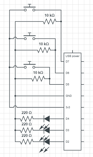
What we want is three buttons, that when pressed will toggle a corresponding LED each. The LED we put in will be red, yellow and green resembling a small traffic light. The buttons are connected to pins D7, D6 and D5 for green, yellow and red respectively and the LEDs to D4, D3 and D2.
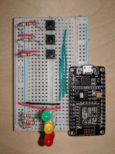
This is a schematic diagram as well as a picture of how the wiring looks on a breadboard. Notice that to make the schematic cleaner, the board omits most of the pins, as they are not used.
Getting into the code
Mongoose supports both JavaScript and C, and the difference for what we are doing here is minimal, but as I am more accustomed to working with JavaScript that will be my language of choice here.
First we need to establish what pins we want to use and set them up. On the board the pins are labeled as D3 or D7 for instance, but Mongoose works with the GPIO number of the pin, so you have to use a map between the two pin numbers. NodeMCU has this map as part of their documentation.
The setup code needed for this project looks like this
load('api_gpio.js');

let GREEN = "green";
let YELLOW = "yellow";
let RED = "red";

let state = {
  "green": false,
  "yellow": false,
  "red": false
};

// Setup input and output pins
let GREEN_INPUT  = 13; // Pin D7
let YELLOW_INPUT = 12; // Pin D6
let RED_INPUT    = 14; // Pin D5

let GREEN_OUTPUT  = 2; // Pin D4
let YELLOW_OUTPUT = 0; // Pin D3
let RED_OUTPUT    = 4; // Pin D2

let OUTPUT_MAP = {
  "green": GREEN_OUTPUT,
  "yellow": YELLOW_OUTPUT,
  "red": RED_OUTPUT
};

GPIO.write(GREEN_OUTPUT, 0);
GPIO.write(YELLOW_OUTPUT, 0);
GPIO.write(RED_OUTPUT, 0);

GPIO.set_mode(GREEN_OUTPUT, GPIO.MODE_OUTPUT);
GPIO.set_mode(YELLOW_OUTPUT, GPIO.MODE_OUTPUT);
GPIO.set_mode(RED_OUTPUT, GPIO.MODE_OUTPUT);
Here state is a map deciding if a given LED is turned on or not. This section is mostly setup for the next part, and in the end we set all the LEDs to off.
This next piece of code takes care of handling the input and toggling the LEDs.
GPIO.set_button_handler(GREEN_INPUT, GPIO.PULL_UP, GPIO.INT_EDGE_NEG, 50, function(x) {
  buttonPressed(GREEN);
}, true);

GPIO.set_button_handler(YELLOW_INPUT, GPIO.PULL_UP, GPIO.INT_EDGE_NEG, 50, function(x) {
  buttonPressed(YELLOW);
}, true);

GPIO.set_button_handler(RED_INPUT, GPIO.PULL_UP, GPIO.INT_EDGE_NEG, 50, function(x) {
  buttonPressed(RED);
}, true);

function buttonPressed(color) {
  state[color] = !state[color];
  triggerStateChange();
}

// Turns LED on or off as applicable.
function triggerStateChange(){
  GPIO.write(OUTPUT_MAP[GREEN], state[GREEN]);
  GPIO.write(OUTPUT_MAP[YELLOW], state[YELLOW]);
  GPIO.write(OUTPUT_MAP[RED], state[RED]);
}
Here GPIO.set_button_handler(...) listens to inputs on a specific pin, and then executes a function if the button attached to the pin is pressed. The first argument is the pin it is listening on, and the second argument is the pull type. In this case the pull type is GPIO.PULL_UP, so the function is executed when the input pin goes from low to high. Alternatively we could have used GPIO.PULL_DOWN, and then the button should have connected GND and the pin, with a resistor from the pin to 3v3, see sparkfuns website for more details.
The third argument says what interrupt type the handler should listen for, but honestly I do not know what that means, however GPIO.INT_EDGE_NEG gives the desired result.
Due to mechanical and physical issues, push buttons can flicker when being pressed, so the board might interpret that as multiple events for one click. To combat that the fourth argument is a debounce time, which is a time where the board will ignore new input on this pin. You can read more details about debounce on the Arduino website.
This is my intuition about how this function works anyway, I might have gotten nuances wrong, and in that case please reach out to me, but the documentation of the function is lacking in explanations when you are not used to working with electronics.
Finally the set_button_handler(...) takes a call back function that it executes when the button is pressed.
The buttonPressed(color) function simply updates the state by toggling the color entry, and then calls triggerStateChange() which switches all the lights in accordance with the state of the lights color.
Getting the code onto the board
It is all well and good that we got a board wired up and some code that allegedly works, but let us combine the two and switch some lights on.
First off we have to flash the device with the Mongoose OS. To do this, you need to install mos from the Mongoose website and make sure that it is part of your PATH in your terminal. Here I will walk through install the app we build using the command line, but you can also use the mos GUI.
Once mos is installed, plug in your esp8266 board with USB and run the following command.
mos flash esp8266
This will download the Mongoose demo app and install Mongoose OS and the demo app to your board. The demo app is a simple app that blinks the on-board LED every second. To install our app, save it as init.js and issue the following command from the directory where it is saved.
mos put init.js
That installs the app, but you still need to reboot the board for the change to take effect. You can achieve this by pressing the RST button next to the USB connection on the board.
With all this in place, it is possible to control your very own very small traffic light!
Admittedly that is not super impressive, but it gives an idea about how you would work with Mongoose OS on an esp8266 board.